

A common question from clients and installers new to working with aluminum is how our aluminum soffits are installed. Our Tongue and Groove Planks for Soffits are designed to install much like traditional tongue and groove materials, such as wood.
Below is a quick guide that addresses many of the common installation questions we receive. For detailed techniques and best practices, please refer to our full installation guide. Proper installation ensures optimal performance and long-term durability.
Access Panels and Light Fixtures
Understanding the Basics
Types of Tongue & Groove Planks
Tongue & Groove refers the the attachment system used, very similar to a traditional wooden siding plank.
We offer three types of tongue & groove planks, with a few variations in width, length and whether or not the plank is perforated.
All of the different options can be found in the list below:
|
Width |
Plank Profile |
Depth (w/ Quick Screen Clips) |
Length(s) |
|
2 1/2″ (64 mm) |
V-Groove |
9/16″ (14 mm) |
12′ |
|
2 1/2″ (64 mm) |
V-groove, Perforated |
9/16″ (14 mm) |
12′ |
|
4″ (102 mm) |
V-Groove |
9/16″ (14 mm) |
12′ / 24′ |
|
6″ (152 mm) |
V-Groove |
9/16″ (14 mm) |
12′ / 24′ |
|
6″ (152 mm) |
V-Groove, Perforated |
9/16″ (14 mm) |
12′ / 24′ |
|
6″ (152 mm) |
Smooth Plank |
9/16″ (14 mm) |
12′ / 24′ |
|
6″ (152 mm) |
Smooth Plank, Perforated |
9/16″ (14 mm) |
12′ / 24′ |
|
6″ (152 mm) |
Channel Plank |
9/16″ (14 mm) |
12′ / 24′ |
Expansion and Contraction
All of our planks and trim components are made from aluminum, and therefore expand and contract at different values depending on temperature. To ensure successful installation, all planks must be installed to accommodate the approximate ¼” (6mm) movement over 24’ (7.3m), measured at a 54°F (30°C) temperature range.
For more information, please see the expansion and contraction tables located at the bottom of our Tongue & Groove Plank Installation Guide.
Attachment
Tongue & Groove planks should be fastened to a secure substrate, such as a framing member, sheathing, furring strips or similar. Our products should never be installed directly onto insulation.
#10 fasteners are the recommended fastener, but always consult the project engineer, architect or authority having jurisdiction to understand the project specific fastening requirements. Typical spacing for the planks are 32” O.C. for typical wind loads and 16” for higher wind loads. For trim components (including Starter Strip), typical spacing is 16” O.C and 24” O.C. for direct to truss.
Trims
Depending on the orientation of the planks, you’ll have a few different options when it comes to trims. If you are new to installing soffits, the main takeaway are the two different styles of trims we recommend for soffits: Craftsman & Traditional.
Precision, Craftsman, and Traditional Styles
Craftsman and Traditional refer to trim styles, each representing the final aesthetic after installation.
An easy way to visualize these is by thinking of small (Precision, not available for soffits), medium (Craftsman), and large (Traditional) trims. The choice depends entirely on the desired aesthetic and the job site’s requirements.
Precision trims deliver a crisp, modern look, while Traditional trims provide greater flexibility, accommodating various installation conditions with ease and offering a more classic appearance. Craftsman trims strike a balance, blending the clean lines of Precision with the flexibility of Traditional trims.
The graphic below illustrates two possible plank orientations: parallel and perpendicular. Each orientation requires a different type of trim, and the graphic outlines the available options for each.

Ventilation
Ventilation is always recommended for soffits, as they improve air circulation and prevent issues like mold and rot. The minimum ventilation your soffit will need depends on your local building codes.
Our tongue and groove planks all have the same attachment and can be mixed and matched based on the amount of ventilation needed and the desired aesthetic. The following graphic shows all of our different planks available.

Installation
Parallel to the Building
Starting a run
For soffit applications that feature the planks running parallel to the building, you begin with the outside edges. Choose between a standard J-track or our Two-Piece J-track perpendicular to the planks or around penetrations and cutouts. On regular conditions, fasten every 16″ O.C. with a #10 Pan Head Screw. Refer to our wind load tables for specifics.
Next, either a Traditional Starter Strip or Precision Starter J-Track is used between the J-tracks. These trims feature a male end for the first Tongue & Groove Plank to be installed onto. Under regular conditions this trim is fastened every 32″ O.C. with a #10 Pan Head Screw. Please refer to our installation guide for wind load tables.
Planks are installed next, ensuring they fully engage onto the starter trim installed in the previous step. All planks are fasted via our Quick Screen Clips and #10 Pan Head Screws every 32″ O.C. under regular conditions. Hard fasten only one point preferably near the center of each plank.
Ending a Run
Before the last plank, install the Termination Set, fastening at 16″ O.C. under regular conditions. View our wind load tables for specifics. Confirm the trim component caps will cover the last plank, and adjust accordingly. Finish off the trims with caps from the two-piece sets.

Perpendicular to the Building
Starting a Run
For soffit applications that feature the planks running perpendicular to the building, you begin with the closest and farthest sides of the building. Choose between a standard J-track or our Two-Piece J-track and install perpendicular to the planks, or around penetrations and cutouts. On regular conditions, fasten every 16″ O.C. with a #10 Pan Head Screw. Refer to our wind load tables for specifics.
Next, either a Back-to-Back Starter strip is installed in the middle of the area to achieve equal width ends. This trim features a male end on either side of the trim for our Tongue & Groove Planks to engage onto. Under regular conditions this trim is fastened every 16″ O.C. with a #10 Pan Head Screw. Please refer to our installation guide for wind load tables.
Planks are installed next, ensuring they fully engage onto the starter trim installed in the previous step. All planks are fasted via our Quick Screen Clips and #10 Pan Head Screws every 32″ O.C. under regular conditions. Hard fasten only one point preferably near the center of each plank.
Ending a Run
Before the last plank, install the Termination Set, fastening at 16″ O.C. under regular conditions. View our wind load tables for specifics. Confirm the trim component caps will cover the last plank, and adjust accordingly. Finish off the trims with caps from the two-piece sets.

Access Panels and Light Fixtures
Access Panels
Access panels in either plank configuration, parallel or perpendicular to the building, will always require the following trim components:
- Back-to-Back Starter Trim x1
- Termination Sets x2
- J-Track x6
Lets begin with the outside end of this detail, the section that is connected to the rest of the soffit. The first step is to understand where the Termination Set will go. Termination Sets always run parallel to the planks (not the building), and on the side where the male side of the plank has been has been ripped. In our following illustration you can view the condition on the right side of the image. The remaining three sides are trimmed out with our J-Track component, in whatever style is aesthetically desired. Mitering the trims is possible for a clean corner finish, otherwise we recommend utilizing the termination set as the long side of the square.
A quick reminder that all these trims (including the base of the Termination Set) should be installed before the planks.
For the access panel itself, begin with the J-tracks, which should be installed perpendicular to the planks. Next, at the center of the panel area, install Back-to-Back Starter Strip parallel to the planks.
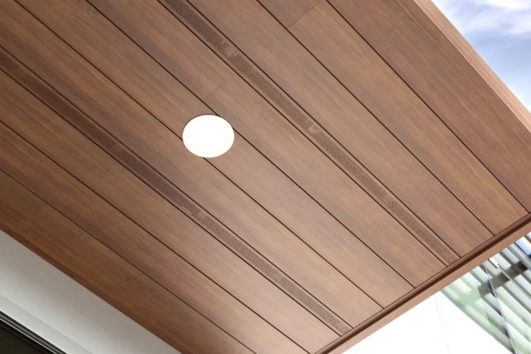
Lights
Installing lights will be dependent on the orientation of the soffit. The graphics below show the different details between the applications.
Perpendicular Soffits

Parallel Soffit

Linear Lights
Linear lights work similar to access panels, were you are using a combination of J-tracks & Termination Sets to enclose the fixture.


Corners
Corners tend to be fairly straight forward in either parallel or perpendicular applications. This condition requires the mitering of the plank and a reveal trim. There are three main options to use:
- Traditional Flat Reveal Set (1-1/2″)
- Craftsman U-reveal Set (3/4″)
- Traditional U-Reveal Set (1-1/2″)
All three sets are two-piece components. The base would be installed prior to the planks, with the cap being installed after the planks.
Artisitic Corners
Traditionally, soffits tend to be one-dimensional. While you can break up patterns and create intrigue with butt joints, you can also create unique designs with non-90° corners. A great example of this is the Immigrant Service Society’s Building, in which the design and construction teams delivered an amazing entrance soffit.
This detail does require precision during the installation, as if the components are not aligned properly, you can end with a larger than ideal reveal or slanted planks.
For soffit applications, you can use the following graphic as a guide. “Horizontal Applications” can be translated to planks that are parallel to building, while “Vertical Applications” refer to planks perpendicular to the building.

Butt Joints
Butt joints have a few benefits, such as minimizing waste of off-cut materials, and the ability to extend a plank run up to 40’ before installing a reveal trim. They can also create intriguing patterns across a large soffit. There are two ways to utilize butt joints: a single butt joint or multiple floating butt joints.
Important note: Improper installation of butt joints can leave a large gap between planks, creating an undesired aesthetic. Specifics found in our installation guide must be followed.

Single Butt Joints
For single butt joints, you can hard fasten the plank directly at the butt joint to mitigate migration. Fasteners
The expansion of the plank would therefore occur at the opposite side of the plank, instead of both ends during normal installations. This method is requires precision and previous experience with butt joint installation.
Alternatively, you can use our backer plate (part of our Butt Joint Kit, sold separately). The backer plate prevents joints from opening up after installation. Fasteners should be installed at the uppermost location of the plank flange, so they don’t interfere with the next plank’s ability to be installed. View the following photo for a detailed view.
Important Note: DO NOT hard-fasten a plank more than one location per plank.

Multiple Floating Butt Joints
Multiple floating butt Joints are also possible with the use of our Butt Joint Kit (sold separately). Furring strips or girts are a must have to allow room for movement.
When using our kit, you are effectively fusing planks together. It is important to note that the expansion factor of approximately ¼” (6mm) movement over 24’ (7.3m), measured at a 54°F (30°C) temperature range still applies.
We recommend planning butt-joints in between furring strips or members to avoid contact which could restrict movement. Additionally, ensure only one location per multiple plank run is hard-fastened.


Wrapping Up
With the right tools, a bit of planning, and attention to detail, installing Longboard T&G soffit planks can be a smooth and rewarding process. Keep expansion and contraction in mind, follow the steps carefully, and your finished result will look clean, sharp, and built to last. For detailed instructions, including wind load tables, fastening instructions and more, make sure to check out the full installation guide below.