
Important Note: For this article, we’ll be referencing many aspects of our HITCH™ installation guide. This document is the “source of truth” and should be referred to when planning and executing the installation. This article is meant as an introductory example rather than detailed steps for your project.
HITCH System Overview
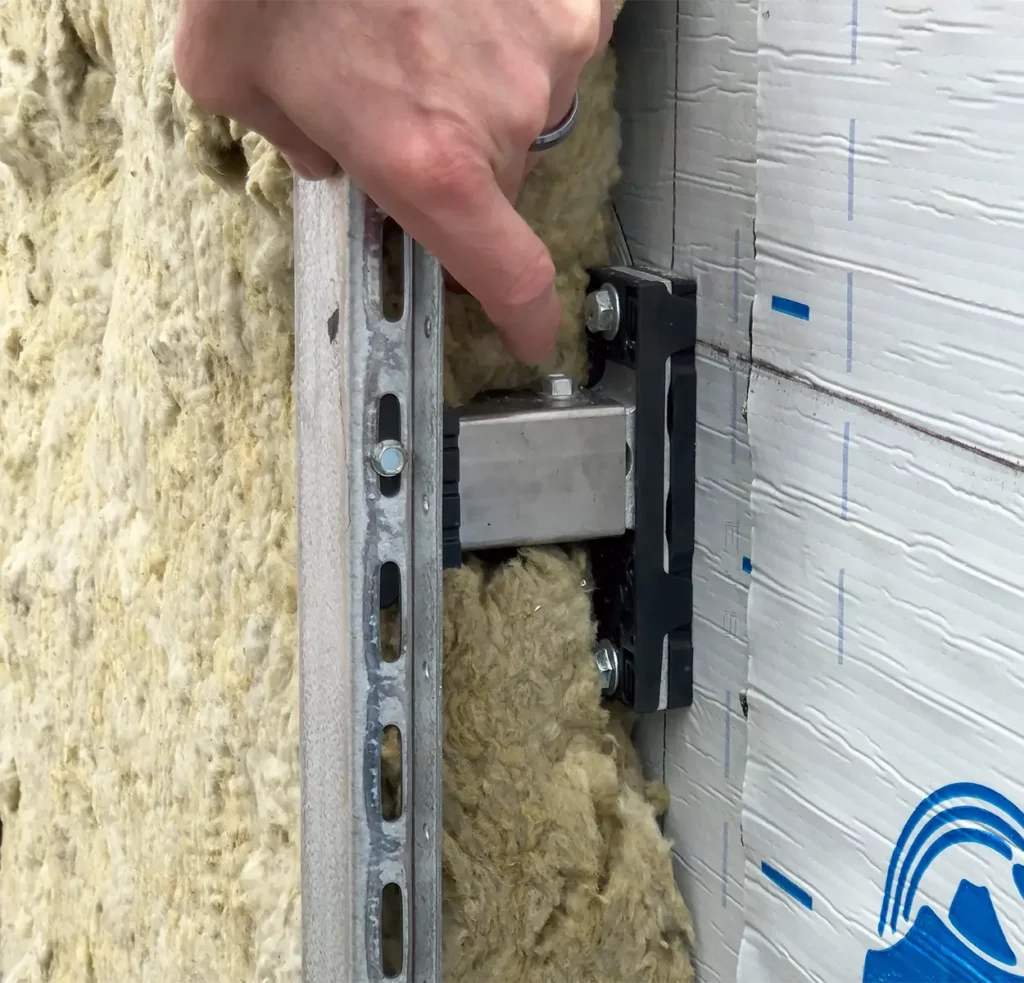
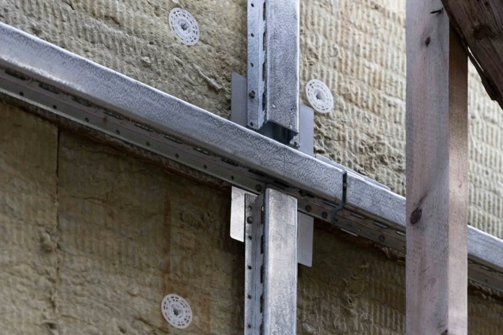
The HITCH™ Cladding Attachment System is a thermally broken, high-performance rainscreen sub-framing system designed for energy-efficient wall assemblies. While it is most commonly used in large-scale commercial, institutional, or healthcare projects, the underlying principles and components remain consistent when applied to any type of construction.
HITCH™ is built from high-tensile aluminum and galvalume steel components that are inherently non-combustible and corrosion-resistant. These materials ensure a long service life, with minimal maintenance, even in demanding climate conditions. The system features integrated thermal breaks at various connection points, maintaining over 90% thermal efficiency.
The modular design of HITCH™ allows for flexible adaptation to different wall depths, cladding types, and structural substrates. With a dead load capacity of up to 16.5 pounds per square foot at wind loads of 35 psf, it offers robust structural support across a wide range of façade applications.
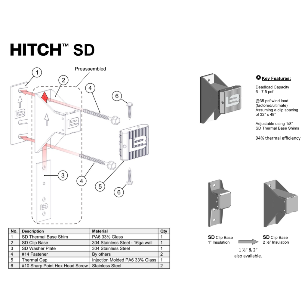
SD Clips
HITCH SD (Standard Duty) clips are optimized for shallow stand-offs and smaller continuous insulation thicknesses, typically from 1″ to 2.5″. These are commonly used in retrofit applications or in residential builds where the insulation layer is modest and cladding weights are lighter.
Despite their smaller size, SD clips maintain high thermal efficiency, thanks to the integrated thermal isolation pads. They are adjusted using stackable shims, allowing up to three shims per clip to achieve a flush plane. While not adjustable through a telescoping mechanism like their HD counterparts, SD clips still maintain precise alignment.
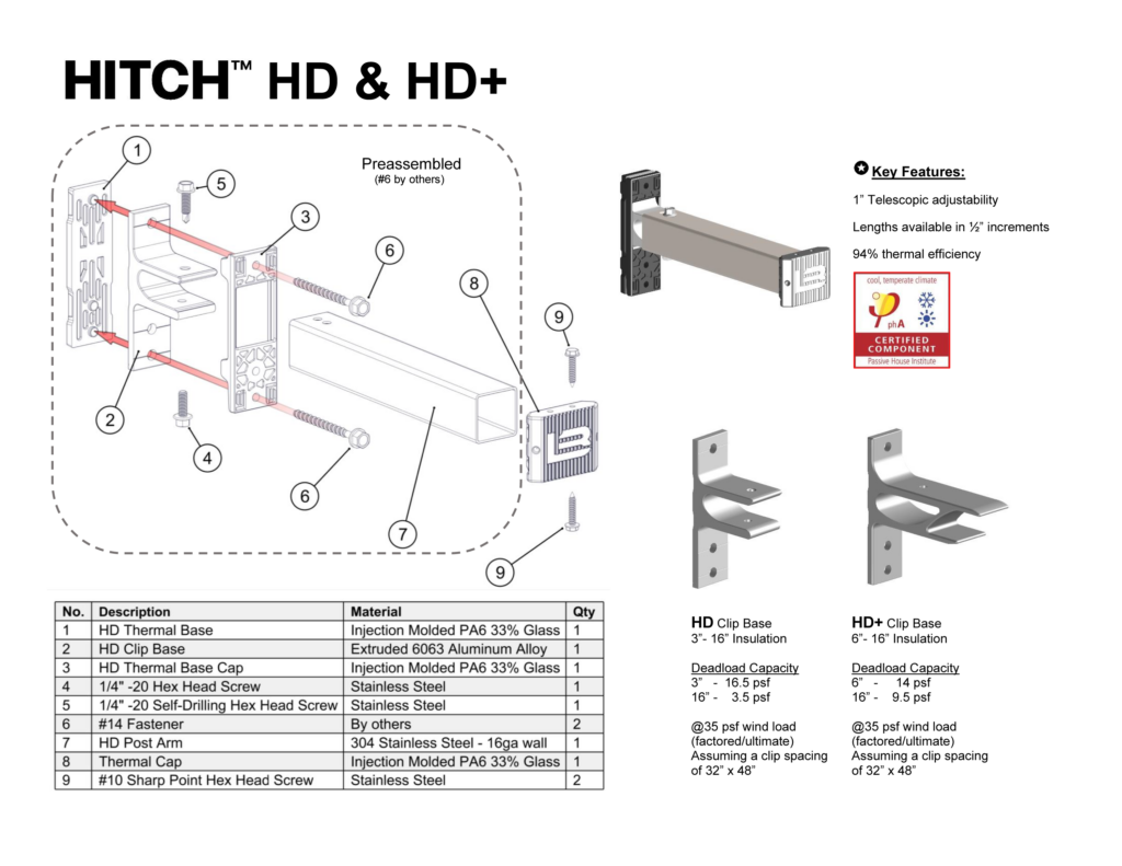
HD & HD+ Clips
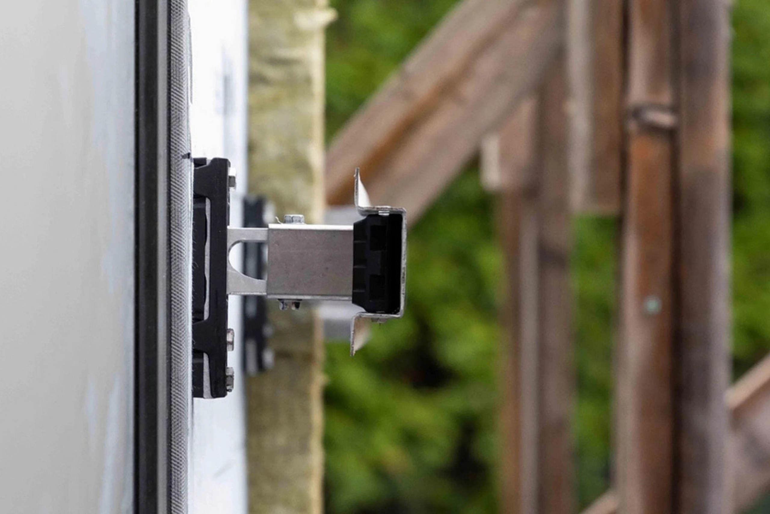
HITCH HD and HD+ clips are designed for thicker exterior insulation systems, accommodating up to 16 inches of continuous insulation. These heavy-duty clips offer both superior load capacity and on-site adjustability.
The HD series includes a telescoping feature that allows up to 1 inch of in-field adjustment, critical for compensating for wall irregularities or tolerances. HD+ provides additional structural strength for higher cladding weights or extreme wind pressure regions, offering a higher dead load capacity at large stand-offs.
Both clip types include robust thermal breaks and caps that prevent heat transfer across the assembly, maintaining high thermal efficiency throughout the wall system. Their strength and versatility make them the default choice for large-scale projects where continuous insulation depth, wind pressure, and cladding weight all demand a higher-performing attachment system.
Determining the Spacing of Our Clips
Determining the appropriate spacing for HITCH clips is a crucial part of the design process and must be tailored to the unique requirements of each project. While this article serves as an introduction, the final layout should always be verified and approved by Longboard’s technical team or a qualified engineer.
To determine spacing, the following information is required:
- Insulation thickness (in inches)
- Cladding weight (if not using Longboard products)
- Cladding attachment requirements (if not using Longboard products)
- Girt clearance (if any)
- Wind load (local design pressures in psf)
- Backup wall structure type (wood, steel, CMU, concrete)
Our technical team uses this data to identify the correct combination of clip type (SD, HD, or HD+), girts, and clip spacing to safely and efficiently support your cladding system.
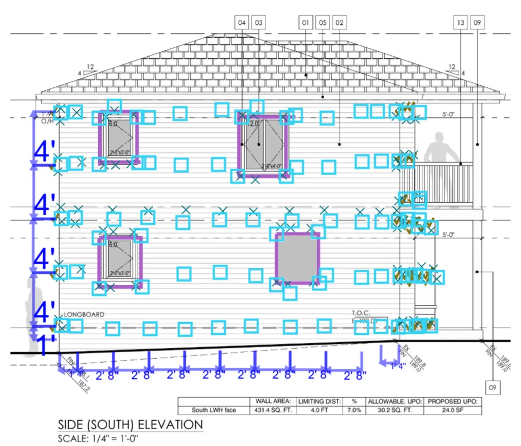
Typical Install Example: 32″ x 48″ Grid
In many standard wall assemblies for commercial or large-scale residential buildings, clip spacing is determined to be 32 inches horizontally and 48 inches vertically. This spacing pattern allows for structural stability, even distribution of load, and efficient thermal performance.
This grid layout minimizes the number of penetrations into backup wall, preserving air and water barrier continuity and simplifying layout during install. Both single & dual girt variations are available, depending on the wind load requirements.
Spacing Around Windows and Openings
Windows and large façade penetrations require special consideration. Depending on the project, clips may be added or omitted. Typically, clips are added around the corners of a window for added support.
The layout will vary depending on application. Always refer to the project-specific clip layout provided by Longboard or your engineer of record to confirm spacing in these critical areas.
General Spacing Guidance for HITCH™ SD
Wrapping Up
In summary, clip spacing is not one-size-fits-all. It requires consideration of structural demands, insulation strategy, cladding system, and local environmental conditions. Longboard’s HITCH system is engineered to adapt to these variables, offering a high-performance, thermally efficient substructure for both residential and commercial applications.