
Utilizing span charts during the design and development phase is integral, particularly in severe weather environments such as South Florida. Longboard’s span charts help architects, engineers, and those responsible for structural drawings clearly understand the performance capabilities of our materials, including when additional attachment points may be required to meet environmental demands and local building code requirements.
Longboard products undergo rigorous testing to ensure the recommendations we provide are the most effective and reliable solutions. While testing requirements may appear to limit attachment spacing, our robust line of components and profile options allows designers with options to achieve greater spans while potentially minimizing the need for additional structural support while minimizing the need for additional structural support.
When span allowances are guessed instead of verified, this can create a few potential scenarios: Overengineering may be done, which may overcompensate structural requirements. With that comes the potential for added costs. Underengineering may also be done, which may affect the long-term performance of the Longboard materials. If the span and load data are confidently understood, this can create efficiency by eliminating unnecessary points of attachment and fasteners that the installer would need to action on the job site.
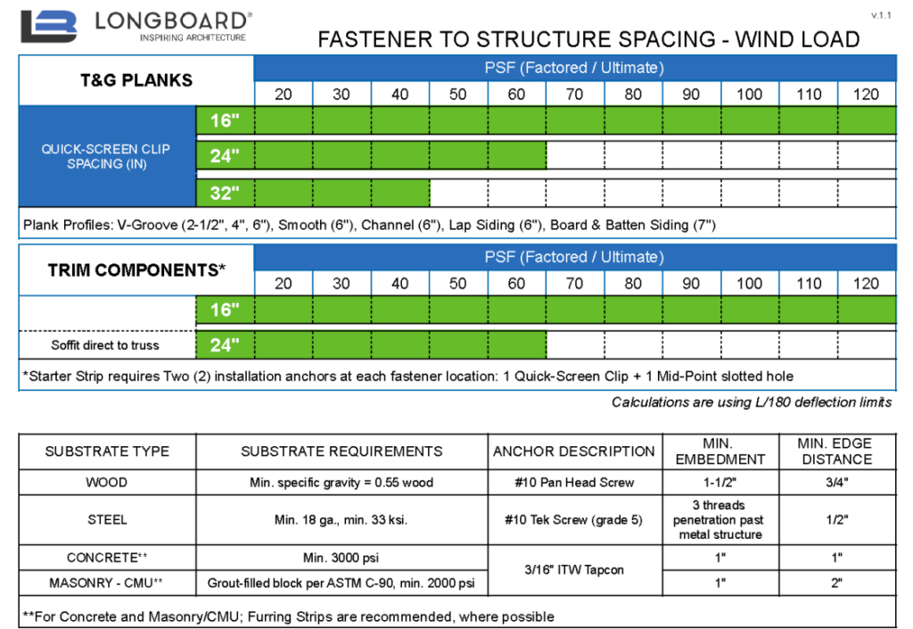
Example of Longboard’s Span Charts for Tongue & Groove Planks
Steps to Reading Span Charts
When working with Longboard, you are supported by a team of trusted advisors who assist with referencing our load tables and span charts to guide projects through the design and development stages. Our team collaborates closely with clients to understand the project’s needs and ensures our materials are specified and attached in the most effective way. Understanding our span charts helps your team to make a thoughtful decision in your design and development process. Here is a how-to properly assess these charts:
- Confirm the Product
Identify the Longboard profile and application listed at the top of the chart, as span allowances vary by product
Lap Siding
Board & Batten
Link & Lock™ Screens & Enclosures
Link & Lock™ Cladding
Tongue & Groove Planks
Tongue & Groove Plank – Textured
Panelboards™
Privacy Beam Cladding - Determine the Design Wind Load (pounds per square foot – PSF)
Reference the required wind load for the project along the top axis of the chart. - Select Fastener Spacing
Choose the desired fastener spacing from the left side of the chart (e.g., 12″, 16″, 24″, 32″). - Check the Allowable Range
Read across the chart to confirm the wind load falls within the green (allowable) zone. White areas indicate closer spacing is required. - Adjust as Needed
If the wind load exceeds the allowable range, reduce fastener spacing until compliance is achieved. - Verify Installation Requirements
Confirm substrate type, fastener specifications, and trim requirements noted in the chart before finalizing the design.

If you have any questions or want to discuss your options, reach out to Longboard’s team of experts or reference the span charts linked in this article.